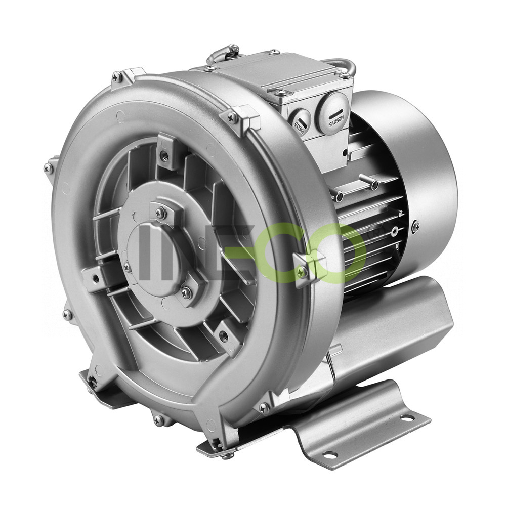
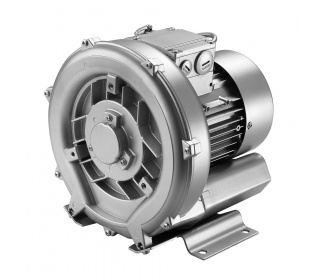
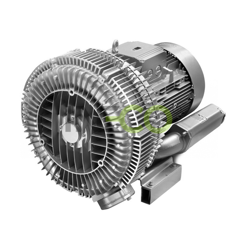
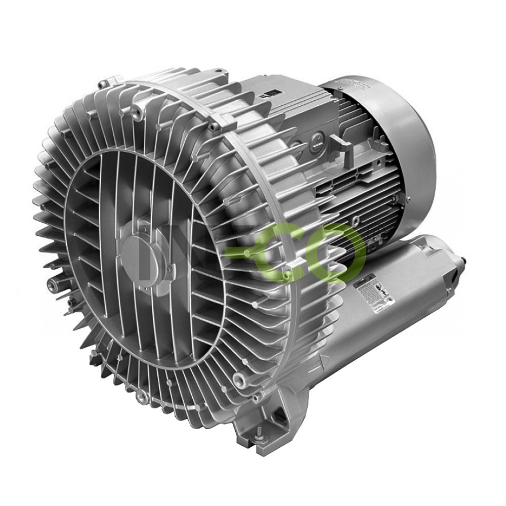
INW single stage ring blowers / vacuum pumps
 INW single stage ring blowers INW 21, INW 31
 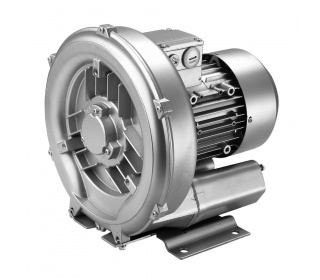 INW single stage ring blowers INW 41
 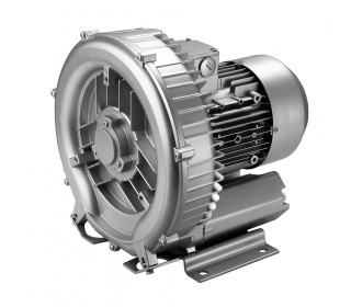 INW single stage ring blowers INW 51
 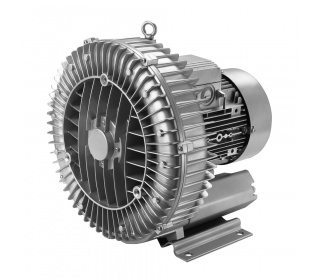 INW single stage ring blowers INW 61, INW 71, INW 73, INW 81, INW 83
 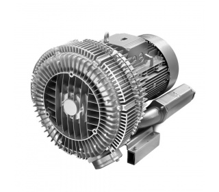 INW single stage ring blowers INW 84
 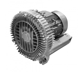 INW single stage ring blowers INW 91, INW 93
 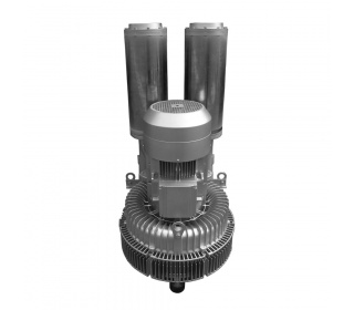 INW single stage ring blowers INW 95
 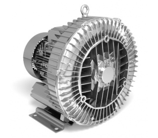 INW single stage ring blowers
 - 5
next

Characteristic
- wide application
- oil free operation
- quiet and low vibration
- low weight
- wide range of types and performance
- easy installation and dismantlement
- minimum moving parts
- simple maintenance
Applications:
- aeration of waste water systems or pond aeration, aquaculture
- agitation (aeration) of the solutions by the galvanic technology
- vacuum cleaning systems – industry cleaners, filters cleaning
- baths - underwater massage, bubble bath, bubble pilar
- drying process, air knifes
- pneumatic conveying system: flour, wheat, powders, synthetic fiber, capsule, etc.
- handling by the suction curve, leafing and sucking by the vacuum, thermograsp packing
- textile industry - vacuum cleaning of production waste
- printing technologies – holding the leaves by sucking
- dental technology - suction device
Principle:
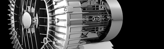
Gas is taken into the device via the suction branch with built-in silencer (1). In the side channel (2) the rotor (3) transfers its speed and gas via centrifugal force is pushed toward the compression chamber. This way, along the spiralroute, gas is repeatedly pressed up to the discharge branch (4), from which it is released. With multi-stage blowers, gas flows through multiple compressor chambers placed behind one another, achieving greater pressure differences.

| Type | Suction
(m3/h) |
Pressure/ vacuum(mbar) |
Motor (IP55)*, 50Hz, (60Hz)** |
Noisi- ness(dB) |
Weight
(kg) |
Blower connec- tion (inner thread) |
||
| Power input | Voltage | Current | ||||||
| (kW) | (V) | (A) | ||||||
| Three phases | ||||||||
| INW 01 H16 * |
55 | 90/80 | 0,2 | 200-240 Δ/345-415 Y | 1,75 Δ/1 Y | 46 | 5 | G 1" |
| INW 11 H16 * |
70 | 120/110 | 0,25 | 200-240 Δ/345-415 Y | 2,1 Δ/1,2 Y | 48 | 7 | G 1" |
| INW 21 H06 | 80 | 110/100 | 0,25 | 200-240 Δ/345-415 Y | 2,1 Δ/1,2 Y | 53 | 8 | G 1¼" |
| INW 21 H16 | 80 | 130/120 | 0,4 | 200-240 Δ/345-415 Y | 2,6 Δ/1,5 Y | 53 | 10 | G 1¼" |
| INW 31 H06 | 110 | 120/110 | 0,55 | 200-240 Δ/345-415 Y |
2,8 Δ/1,6 Y |
55 | 11 | G 1¼" |
| INW 41 H06 | 145 | 120/120 | 0,7 | 200-240 Δ/345-415 Y | 3,8 Δ/2,2 Y | 63 | 13 | G 1½" |
| INW 41 H16 | 145 | 160/160 | 0,85 | 200-240 Δ/345-415 Y | 4,2 Δ/2,4 Y | 63 | 15 | G 1½" |
| INW 41 H26 | 145 | 200/170 | 1,3 | 200-240 Δ/345-415 Y | 5,7 Δ/3,3 Y | 63 | 17 | G 1½" |
| INW 51 H06 | 210 | 100/110 | 0,85 | 200-240 Δ/345-415 Y | 4,2 Δ/2,4 Y | 64 | 19 | G 2" |
| INW 51 H16 | 210 | 170/170 | 1,3 | 200-240 Δ/345-415 Y | 5,7 Δ/3,3 Y | 64 | 21 | G 2" |
| INW 51 H26 | 210 | 190/200 | 1,6 | 200-240 Δ/345-415 Y | 7,5 Δ/4,3 Y | 64 | 22 | G 2" |
| INW 51 H36 | 210 | 270/220 | 2,2 | 200-240 Δ/345-415 Y | 9,7 Δ/5,6 Y | 64 | 25 | G 2" |
| INW 53 H06 | 270 | 40/40 | 0,85 | 200-240 Δ/345-415 Y | 4,2 Δ/2,4 Y | 65 | 19 | G 2” |
| INW 53 H16 | 270 | 110/120 | 1,3 | 200-240 Δ/345-415 Y | 5,7 Δ/3,3 Y | 65 | 21 | G 2” |
| INW 53 H26 | 270 | 150/160 | 1,6 | 200-240 Δ/345-415 Y | 7,5 Δ/4,3 Y | 65 | 22 | G 2” |
| INW 53 H36 | 270 | 230/220 | 2,2 | 200-240 Δ/345-415 Y | 9,7 Δ/5,6 Y | 65 | 25 | G 2” |
| INW 61 H06 | 280 | 180/170 | 1,6 | 200-240 Δ/345-415 Y | 8,5 ∆/ 4,9 Y | 65 | 24 | G 2” |
| INW 61 H16 | 280 | 220/235 | 2,2 | 200-240 Δ/345-415 Y | 9,7 Δ/5,6 Y | 65 | 26 | G 2" |
| INW 61 H26 | 280 | 280/280 | 3,0 | 200-240 Δ/345-415 Y | 12,5 Δ/7,2 Y | 65 | 31 | G 2" |
| INW 71 H06 | 318 | 150/160 | 1,6 | 200-240 Δ/345-415 Y | 8,5 Δ/4,9 Y | 69 | 27 | G 2" |
| INW 71 H16 | 318 | 190/190 | 2,2 | 200-240 Δ/345-415 Y | 9,7 Δ/5,6 Y | 69 | 29 | G 2" |
| INW 71 H26 | 318 | 270/260 | 3,0 | 200-240 Δ/345-415 Y | 12,5 Δ/7,2 Y | 69 | 34 | G 2" |
| INW 71 H37 | 318 | 360/290 | 4,0 | 345-415 ∆/600-720 Y | 9,5 Δ/5,5 Y |
69 | 40 | G 2" |
| INW 73 H06 | 420 | 100/100 | 1,6 | 200-240 Δ/345-415 Y |
8,5 Δ/4,9 Y | 70 | 29 | G 2" |
| INW 73 H16 | 420 | 170/180 | 2,2 | 200-240 Δ/345-415 Y |
9,7 Δ/5,6 Y | 70 | 32 | G 2" |
| INW 73 H26 | 420 | 200/220 | 3,0 | 200-240 Δ/345-415 Y |
12,5 Δ/7,2 Y |
70 | 37 | G 2" |
| INW 73 H37 | 420 | 290/260 | 4,0 | 345-415V ∆/600-720 Y | 9,5 ∆/5,5 Y | 70 | 42 | G 2" |
| INW 81 H07 | 530 | 200/200 | 4,0 | 345-415V ∆/600-720 Y | 9,5 ∆/5,5 Y | 70 | 51 | G 2½" |
| INW 81 H17 | 530 | 300/300 | 5,5 | 345-415V ∆/600-720 Y | 13,3 ∆/7,7 Y | 70 | 61 | G 2½" |
| INW 81 H27 | 530 | 430/320 | 7,5 | 345-415V ∆/600-720 Y | 16,7∆/9,6 Y | 70 | 66 | G 2½" |
| INW 83 H07 | 700 | 140/150 | 4,0 | 345-415V ∆/600-720 Y | 9,5 ∆/5,5 Y | 70 | 52 | G 2½" |
| INW 83 H17 | 700 | 190/200 | 5,5 | 345-415V ∆/600-720 Y | 13,3 ∆/7,7 Y | 70 | 62 | G 2½" |
| INW 83 H27 | 700 | 260/270 | 7,5 | 345-415V ∆/600-720 Y | 16,7 ∆/9,6 Y | 70 | 67 | G 2½" |
| INW 84 H27 | 900 | 180/200 | 7,5 | 345-415V ∆/600-720 Y | 16,7 ∆/9,6 Y | 74 | 87 | G 2½" |
| INW 84 H37 | 900 | 370/280 | 11,0 | 345-415V ∆/600-720 Y | 28,0 ∆/16,2 Y | 74 | 115 | G 2½" |
| INW 91 H07 | 1050 | 190/190 | 8,5 | 345-415V ∆/600-720 Y | 18,2 ∆/10,5 Y | 74 | 108 | G 4" |
| INW 91 H17 | 1050 | 280/290 | 12,5 | 345-415V ∆/600-720 Y | 28,0 ∆/16,2 Y | 74 | 121 | G 4" |
| INW 91 H37 | 1050 | 460/360 | 18,5 | 345-415V ∆/600-720 Y | 37,0 ∆/21,0 Y | 74 | 126 | G 4" |
| INW 93 H07 | 1370 | 110/120 | 8,5 | 345-415V ∆/600-720 Y | 18,2 ∆/10,5 Y | 75 | 98 | G 4" |
| INW 93 H17 | 1370 | 180/190 | 12,5 | 345-415V ∆/600-720 Y | 28,0 ∆/16,2 Y | 75 | 120 | G 4" |
| INW 93 H37 | 1370 | 340/320 | 18,5 | 345-415V ∆/600-720 Y | 37,0 ∆/21,0 Y | 75 | 131 | G 4" |
| INW 94 H27 | 1940 | 110/130 | 15,0 | 345-415V ∆/600-720 Y | 35,0 ∆/20,0 Y | 75 | 187 | G 4" |
| INW 94 H37 | 1940 | 200/220 | 20,0 | 345-415V ∆/600-720 Y | 40,0 ∆/23,0 Y | 75 | 212 | G 4" |
| INW 94 H47 | 1940 | 280/310 | 25,0 | 345-415V ∆/600-720 Y | 52,0 ∆/30,0 Y | 75 | 219 | G 4" |
| INW 95 H27 | 2050 | 170/160 | 15,0 | 345-415V ∆/600-720 Y | 35,0 ∆/20,0 Y | 75 | 220 | G 4" |
| INW 95 H37 | 2050 | 230/250 | 20,0 | 345-415V ∆/600-720 Y | 40,0 ∆/23,0 Y | 75 | 230 | G 4" |
| INW 95 H47 | 2050 | 280/310 | 25,0 | 345-415V ∆/600-720 Y | 52,0 ∆/30,0 Y | 75 | 235 | G 4" |
| Single phase | ||||||||
| INW 01 A11 * |
55 | 80/70 | 0,2 | 200-240 | 1,5 | 46 | 6 | G 1" |
| INW 11 A11 * | 70 | 110/110 | 0,25 | 200-240 | 1,7 | 48 | 8 | G 1" |
| INW 21 A11 | 80 | 130/120 | 0,37 | 200-240 | 2,7 | 53 | 10 | G 1¼" |
| INW 31 A01 | 100 | 120/120 | 0,55 | 200-240 | 3,7 | 55 | 12 | G 1¼" |
| INW 41 A01 | 145 | 120/120 | 0,7 | 200-240 | 4,5 | 63 | 16 | G 1½" |
| INW 41 A11 | 145 | 160/150 | 0,8 | 200-240 | 5,2 | 63 | 16 | G 1½" |
| INW 41 A21 | 145 | 190/150 | 1,1 | 200-240 | 7,3 | 63 | 18 | G 1½" |
| INW 51 A11 | 210 | 160/160 | 1,1 | 200-240 | 7,3 | 64 | 22 | G 2" |
| INW 51 A21 | 210 | 200/190 | 1,5 | 200-240 | 9 | 64 | 26 | G 2" |
| INW 53 A21 | 270 | 140/150 | 1,5 | 200-240 | 9 | 65 | 26 | G 2" |
* Model INW 01 and INW 11 have protection category IP54
** 60 Hz please request this information.
INW ring blowersDatasheets (pdf/2MB)
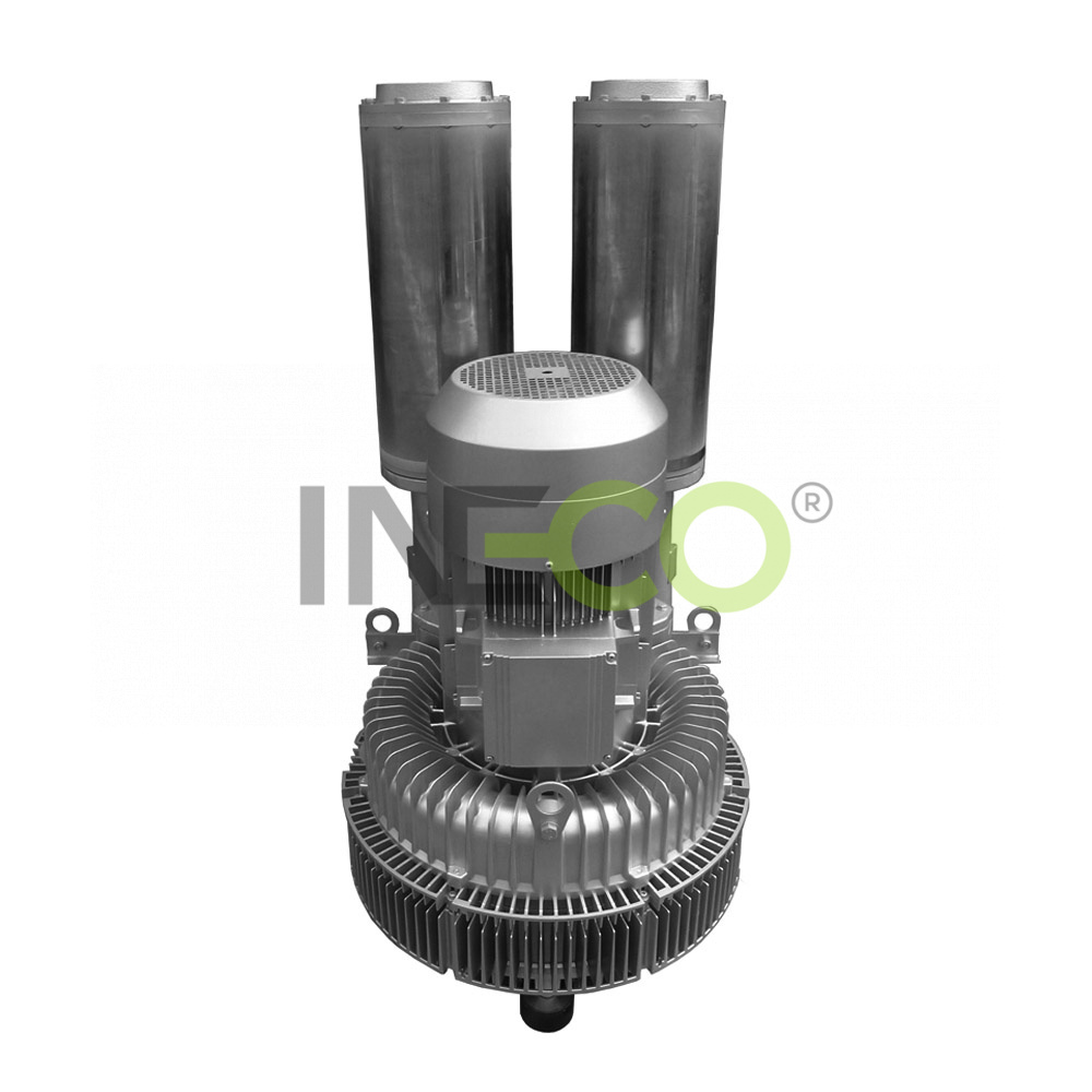
Double stage blowers and exhausters INW provide higher performances.
Single stage ring blowers/exhausters INW can be applied as vacuum pump and compressor in continuous operation over the total stated performance curve range. The motors are available as standard for the input voltage range of 50 and 60 Hz and for protection category IP 55 (protection against dust and splashing water) except for models INW 01 and INW 11, which have a degree of protection IP 54.
Motors are designed according to the DIN EN 60 034/ IEC 34-1 and temperature class F. For the three phase machines the tolerance +/- 10% for fixed voltage and for +/- 5% voltage range. The single phase machines are designed with a +/- 5% tolerance. If only 90% of the maximum allowed pressure will be used for continuous operating then the allowed voltage range add to +/- 10%. The frequency tolerance is maximum +/- 2%.
 |
|
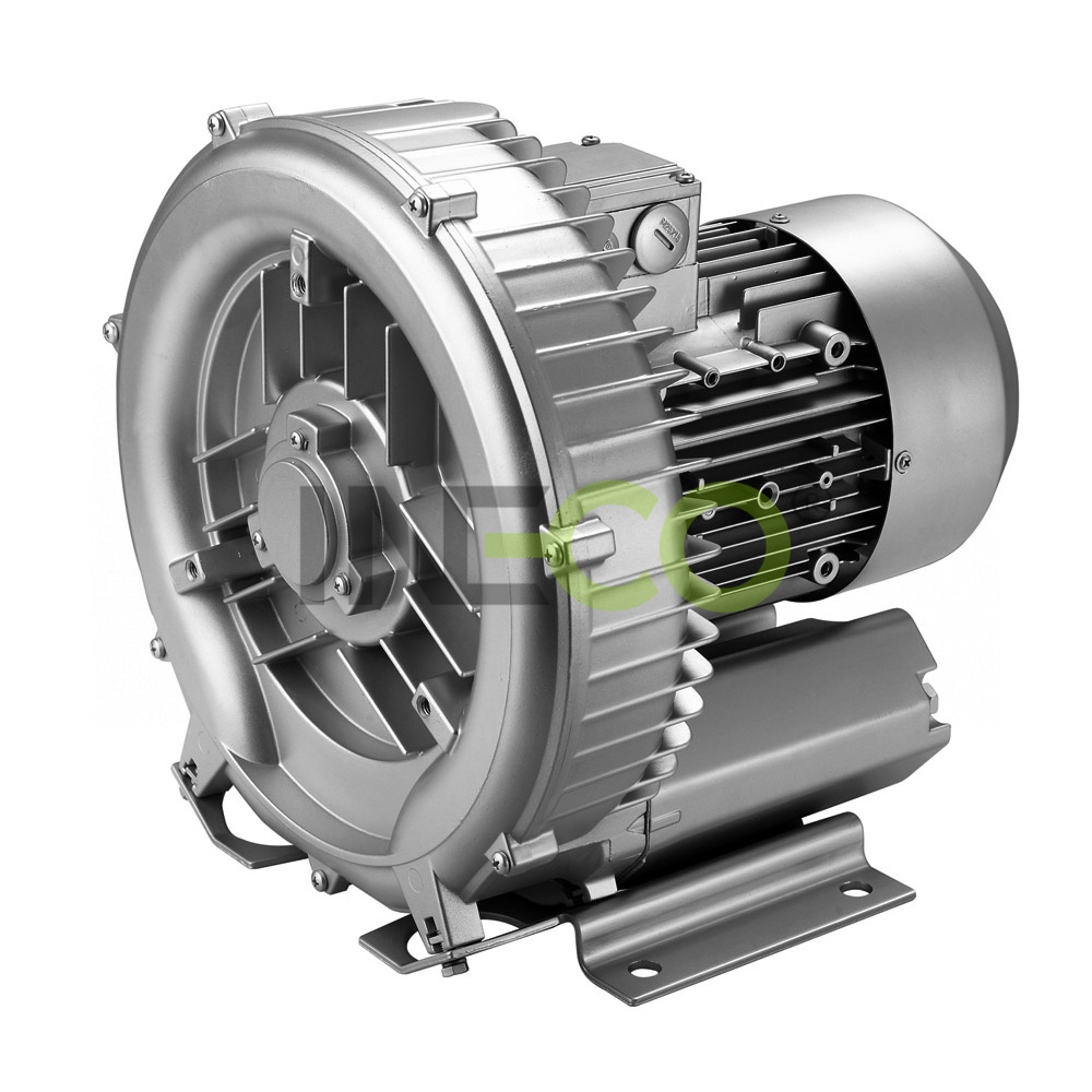
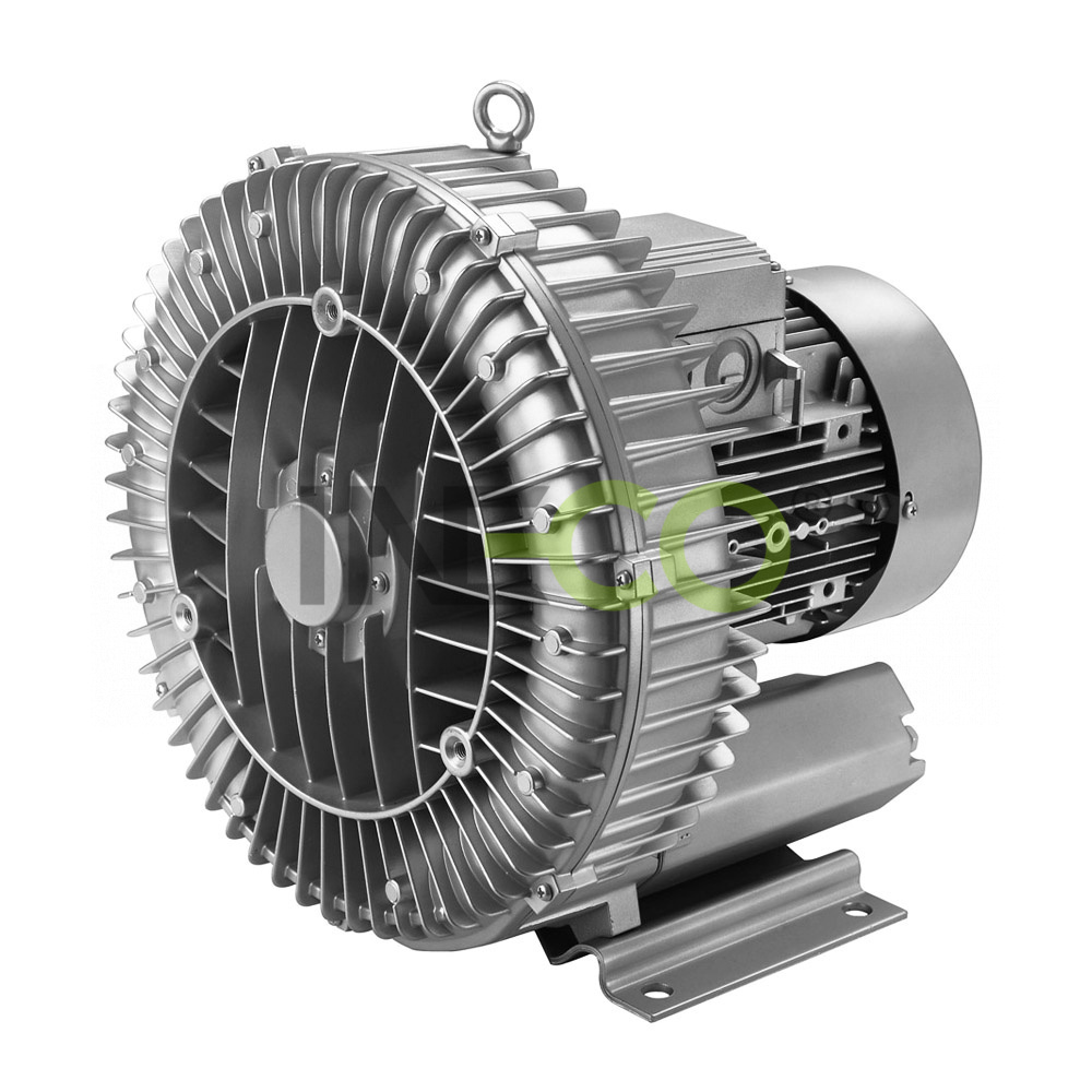
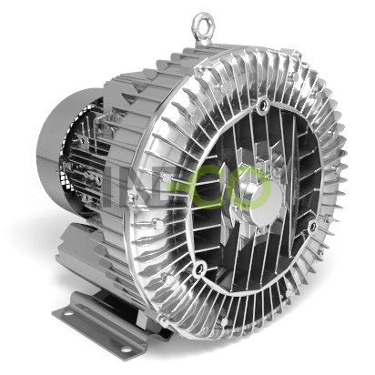
Side channel single stage blowers/pumps INW
|
 |
| Side channel single stage blowers/pumps INW |  |
|
|
INW blowers/exhausters meet Directive 2002/95/EC of European Parliament and of the Council of 27 January 2003 on the restriction of the use of certain hazardous substances in electrical and electronic equipment. |
INW blowers/exhausters conform to the European Community’s Machinery Directive (CE). |